| C2 | C3 | Controller Type |
| 0 | 0 | Reserved |
| 0 | 1 | Bank switching controller (analog joystick, head-mounted tracker etc.) |
| 1 | 0 | "Tempest" rotary controller |
| 1 | 1 | "Standard" Jaguar joypad controller (or nothing connected) |
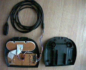
This page describes how you can modify your normal Joypad to make it capable to respond with any of the 4 possible controller types.
I've enhanced a Joypad-schematic drawn by Elmar Hilgart to explain the necessary modifications:
 |
|
Here is a list of the necessary parts:
 |
|
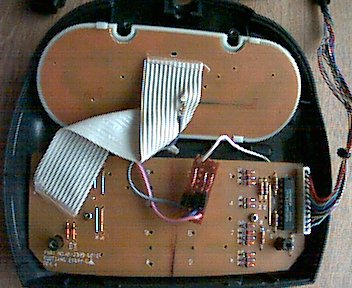
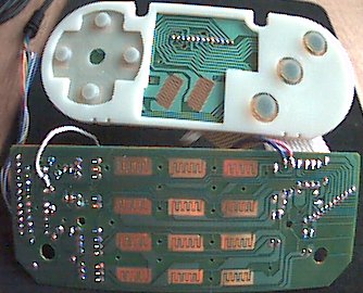
Then connect the white, pink and blue wires to the Number-pad-PCB:
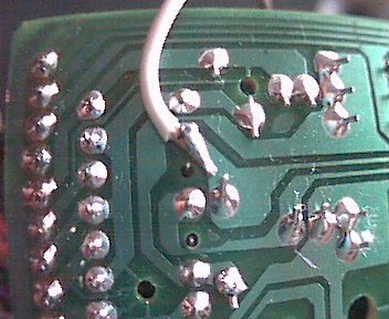
Connect the white wire to pin 2 of chip U1 (the 74HCT244):
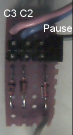
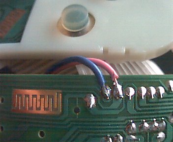
Connect the pink and the blue wire to these soldering points near to the 'Number 3' contact area:
Now cut of the wire number 10 of P2 (the ribbon cable connection between the Number-pad PCB and the Thumb-pad PCB). Counting from the outside!
Now solder the gray wire to the part of wire number 10 coming from the Thumb-pad PCB.
That's all! You can test the modification with my TeamTap-tool