So Tx of the JagLink is connected to pin 2B (UART_TXD), Rx is connected to pin 3B (UART_RXD), Gnd to 6B (GND) and +5V to 1B (Vcc, 50 mA maximum load).
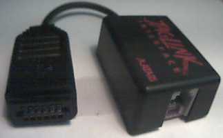
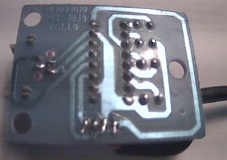
To the left you can see the DSP-port plug with it's 12 PCB-contacts.
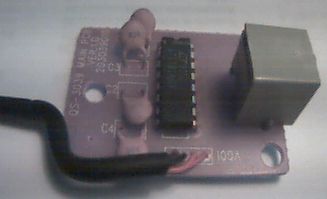
To the right there is the case for the single-sided PCB with the MAX232-compatible LT1181ACN chip, four 100 nF capacitors and the RJ45 Western socket. Only the four inner wires of the RJ45 socket are used.
|
|
|
The Jaguar's external DSP connector is a custom 12-pin, two row edge
connector. The top row is row A, the bottom row is row B. Pin 1 is on the
left, pin 6 on the right when looking at the console from the rear.
So Tx of the JagLink is connected to pin 2B (UART_TXD), Rx is connected to pin 3B (UART_RXD), Gnd to 6B (GND) and +5V to 1B (Vcc, 50 mA maximum load). |